The cables should be labeled with as: “C” (Common) “R” (Reverse) “W” (White/Heat) “G” (Green/Cool). It is essential to ensure all the wiring diagram is connected correctly and secured. You can either add or connect cable nuts or butt connectors for this work. Make sure to join the proper cable to each terminal. 2.
130 AC/REF ideas | refrigeration and air conditioning, hvac air conditioning, air conditioner maintenance
Dometic air conditioner user manual (24 pages) Air Conditioner Dometic DuraSea DCA36D Installation, Start-Up & Service Manual. Condenser unit (28 pages) … WIRING DIAGRAMS Unit Wiring Diagrams 2. 3313189.000 & 3313189.015 LCD SZ Electron- ic Control Kit Wiring Diagram Cool/Furnace 1. H540315 & H540316 Wiring Diagram FIG. 30 FIG. 28 Electronic

Source Image: pinterest.com
Download Image
The Replacement Single Zone Thermostat for Dometic RV Air Conditioners # DMC79FR is a single zone 3 wire thermostat like the one you are describing. I have attached the wiring diagram for this thermostat and the control box below for your reference. expert reply by: Robin H. Dometic Control Box Wiring. (click to enlarge) Dometic Thermostat Wiring.

Source Image: pinterest.com
Download Image
Dometic CFX3 25 Powered Cooler – 25L – ShopTinyHouses.com Air Conditioner Dometic 640312 Series Installation And Operating Instructions Manual. Roof top unit (12 pages) … Value Air Distribution Box (ADB), Mechanical Wiring Diagrams 5 Wiring Diagrams Compressor This section provides the wiring diagrams for the Motor product. GRN/YEL O.L. Compressor 6 Pin Conn Motor GRN/YEL O.L. 6 Pin Conn Comp

Source Image: autoparts.coggintoyota.com
Download Image
Dometic Ac Wiring Schematic
Air Conditioner Dometic 640312 Series Installation And Operating Instructions Manual. Roof top unit (12 pages) … Value Air Distribution Box (ADB), Mechanical Wiring Diagrams 5 Wiring Diagrams Compressor This section provides the wiring diagrams for the Motor product. GRN/YEL O.L. Compressor 6 Pin Conn Motor GRN/YEL O.L. 6 Pin Conn Comp Place the unit on the roof. Page 11 INSTALLATION PROCEDURE 6. Installation Of Divider Plate FIG. 15 Control a. Measure the ceiling to roof thickness: Cables If distance is 2.0″ – 3-3/4″, remove perfo- rated tab from divider plate. See (FIG. 17). If distance is 3-3/4″ – 5-1/2″, remove no Furnace tabs. Wires b.
Hvac Temperature Control Panel | Part #559000E190 | Toyota Auto Parts
Overall, following the wiring pathway on a Dometic AC wiring diagram allows for a better understanding of how the system operates and helps troubleshoot any issues that may arise. It’s important to refer to the specific diagram for the AC unit being worked on, as different models may have variations in the wiring configuration. 130 AC/REF ideas | refrigeration and air conditioning, hvac air conditioning, air conditioner maintenance

Source Image: pinterest.com
Download Image
21 RV Thermostat upgrade ideas | thermostat, thermostat wiring, rv Overall, following the wiring pathway on a Dometic AC wiring diagram allows for a better understanding of how the system operates and helps troubleshoot any issues that may arise. It’s important to refer to the specific diagram for the AC unit being worked on, as different models may have variations in the wiring configuration.

Source Image: pinterest.com
Download Image
130 AC/REF ideas | refrigeration and air conditioning, hvac air conditioning, air conditioner maintenance The cables should be labeled with as: “C” (Common) “R” (Reverse) “W” (White/Heat) “G” (Green/Cool). It is essential to ensure all the wiring diagram is connected correctly and secured. You can either add or connect cable nuts or butt connectors for this work. Make sure to join the proper cable to each terminal. 2.

Source Image: pinterest.com
Download Image
Dometic CFX3 25 Powered Cooler – 25L – ShopTinyHouses.com The Replacement Single Zone Thermostat for Dometic RV Air Conditioners # DMC79FR is a single zone 3 wire thermostat like the one you are describing. I have attached the wiring diagram for this thermostat and the control box below for your reference. expert reply by: Robin H. Dometic Control Box Wiring. (click to enlarge) Dometic Thermostat Wiring.
Source Image: shoptinyhouses.com
Download Image
Wire, Rear Console Box | Part #821760E120 | Toyota Auto Parts Dometic 3-wire Thermostat Wiring Diagram for Boilers and Heaters. Most modern boilers and water heaters are operated by three-wire thermostats, which are identified by the colors G, W, and R. The “G” or green wire is a notable aspect that distinguishes between two-wire and three-wire thermostats, and it is often utilized for regulating fans.

Source Image: autoparts.venturatoyota.com
Download Image
Wire, Roof, No. 1 | Part #8217148R30 | Toyota Auto Parts Air Conditioner Dometic 640312 Series Installation And Operating Instructions Manual. Roof top unit (12 pages) … Value Air Distribution Box (ADB), Mechanical Wiring Diagrams 5 Wiring Diagrams Compressor This section provides the wiring diagrams for the Motor product. GRN/YEL O.L. Compressor 6 Pin Conn Motor GRN/YEL O.L. 6 Pin Conn Comp

Source Image: autoparts.leithtoyota.com
Download Image
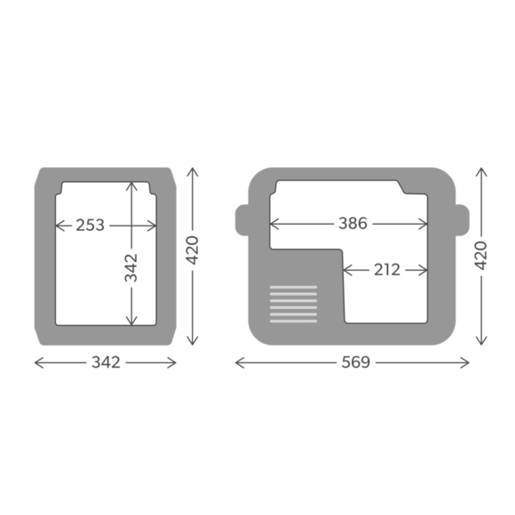
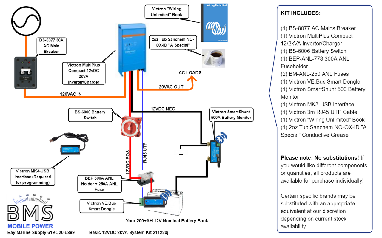
BMS Basic 12V 2KVA System Kit Place the unit on the roof. Page 11 INSTALLATION PROCEDURE 6. Installation Of Divider Plate FIG. 15 Control a. Measure the ceiling to roof thickness: Cables If distance is 2.0″ – 3-3/4″, remove perfo- rated tab from divider plate. See (FIG. 17). If distance is 3-3/4″ – 5-1/2″, remove no Furnace tabs. Wires b.
Source Image: roguevan.com
Download Image
21 RV Thermostat upgrade ideas | thermostat, thermostat wiring, rv
BMS Basic 12V 2KVA System Kit Dometic air conditioner user manual (24 pages) Air Conditioner Dometic DuraSea DCA36D Installation, Start-Up & Service Manual. Condenser unit (28 pages) … WIRING DIAGRAMS Unit Wiring Diagrams 2. 3313189.000 & 3313189.015 LCD SZ Electron- ic Control Kit Wiring Diagram Cool/Furnace 1. H540315 & H540316 Wiring Diagram FIG. 30 FIG. 28 Electronic
Dometic CFX3 25 Powered Cooler – 25L – ShopTinyHouses.com Wire, Roof, No. 1 | Part #8217148R30 | Toyota Auto Parts Dometic 3-wire Thermostat Wiring Diagram for Boilers and Heaters. Most modern boilers and water heaters are operated by three-wire thermostats, which are identified by the colors G, W, and R. The “G” or green wire is a notable aspect that distinguishes between two-wire and three-wire thermostats, and it is often utilized for regulating fans.